ANSYS ICEM CFD
ANSYS ICEM CFD meshing software starts with advanced CAD/geometry readers and repair tools to allow the user to quickly progress to a variety of geometry-tolerant meshers and produce high-quality volume or surface meshes with minimal effort. Advanced mesh diagnostics, interactive and automated mesh editing, output to a wide variety of computational fluid dynamics (CFD) and finite element analysis (FEA) solvers and multiphysics post-processing tools make ANSYS ICEM CFD a complete meshing solution. ANSYS endeavors to provide a variety of flexible tools that can take the model from any geometry to any solver in one modern and fully scriptable environment:
- mesh from dirty CAD and/or faceted geometry such as STL,
- efficiently mesh large, complex models,
- hexa mesh (structured or unstructured) with advanced control,
- extended mesh diagnostics and advanced interactive mesh editing,
- output to a wide variety of CFD and FEA solvers as well as neutral formats.
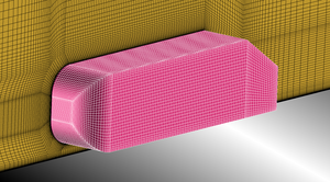
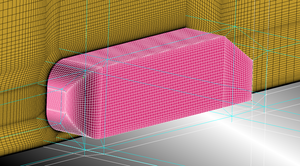
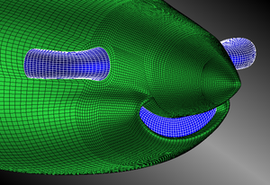
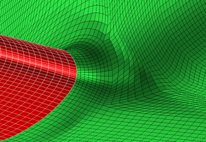
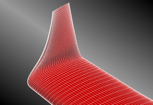
Following pictures show meshes obtained with the Hexa module of ANSYS ICEM CFD, which can generates multi-block hexahedral grids. It is still widely used for industrial applications, especially in aerospace and automotive fields, where high quality fully-structured grids are required.
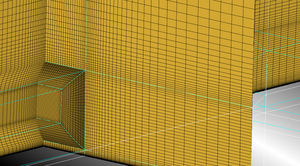
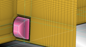
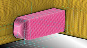
1 The Ahmed body is a well documented test case of the CFD literature. An H-grid meshing strategy has been chosen for the computational flow domain around the Ahmed body. The blocking topology is defined by edges coloured in white and light blue. An O-grid around the Ahmed body has been added to capture the viscous effects. First cell height has to be adjusted according to the most suitable near-wall treatment (wall functions or near-wall modeling) chosen and the corresponding turbulence model.
Next four pictures show the volume mesh on a vertical cutting plane moving from the front to the rear part of the Ahmed body.
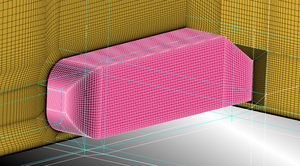
2 Snapshots of the surface mesh of a single-engine turbine-powered business aircraft are shown below. Meshing complex geometries using a fully-structured mesh generator is definitely a very demanding work and is time consuming. Despite the complexity of the geometry all details were taken into account and were well represented.
Pictures represent the nose of the aircraft with the air intake and the engine exhausts, the wing-fuselage junction and the winglet.
