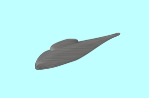
ROBIN Helicopter
Over the last decades, Computational Fluid Dynamics (CFD) has evolved as a prediction tool in the early design phase of the aircraft. The flow field surrounding helicopters is unsteady in nature and has multiple stagnation and separation points due to its complex geometry. And it comprise a wide range of speeds, from almost zero to almost Mach 0.7-0.9, due to the speed difference between the rotor blade root and the rotor blade tip in forward flight.
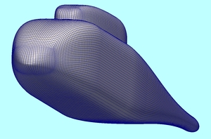
The ROtor-Body-INteraction (ROBIN) geometry depicts a realistic helicopter configuration with four blades. The geometry, which was developed at NASA, is analytically derived with equations [5]. The blade has a rectangular platform shape with an NACA 0012 airfoil section. The ROBIN fuselage has been extensively used in experiments. A large amount of experimental results obtained by wind tunnel testings are available [5, 6].
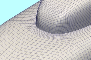
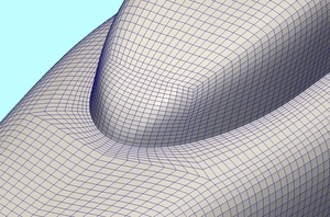
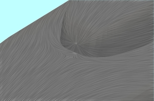
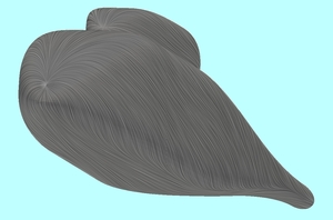
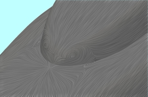
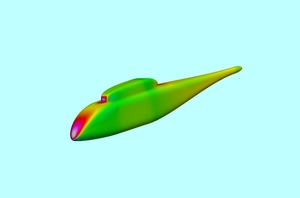
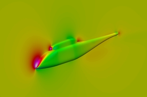
Pictures of this article belong to the isolated fuselage entry-level computation. Left pictures show the front intersection between fuselage and pylon, middle pictures the ROBIN helicopter geometry and right pictures the rear intersection between fuselage and pylon. The first series of images shows the fully-structured hexahedral grids on the fuselage and pylon geometry components of the ROBIN helicopter, the second series the pressure contours and the third series the surface streamlines calculated from the wall shear stress. Hovering over some of the thumbnails will enlarge the pictures.
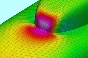
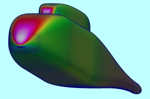
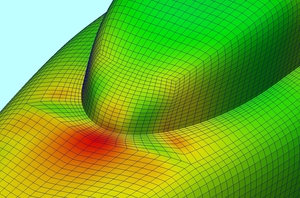
Finally some pictures showing the ROBIN helicopter moving in forward flight attitude.
To consider the complete rotor-fuselage configuration is much more challenging, because of the geometrical complexity and the resulting grid requirements, both in terms of dimensions and generation effort, the need to handle the relative motion between rotor blades and fuselage, thus requiring sophisticated numerical techniques, like the overlapping Chimera grid method or the sliding mesh approach. Exhaustive literature regarding this specific test case exists, and in particular:
[1] Biava, Massimo and Khier, Walid and Vigevano, Luigi. CFD Prediction of Air Flow Past a Full Helicopter Configuration. Aerospace Science and Technology, DOI: 10.1016/j.ast.2011.08.007, 2011.
[2] Steijl, R., Barakos, G., and Badcock, K.. A Framework for CFD Analysis of Helicopter Rotors in Hover and Forward Flight. International Journal for Numerical Methods in Fluids, Vol. 51, No. 8, pag. 819-847, 2006.
[3] Steijl, R., Barakos, G., Badcock, K.J., and Kirkham, D.. A CFD Framework for Analysis of Helicopter Rotors. AIAA Paper 2005-5124, 23rd AIAA Applied Aerodynamics Conference, Toronto, Ontario, 6-9 Jun. 2005.
[4] Bum Seok Lee and Mun Seung Jung and Oh Joon Kwon and Hee Jung Kang. Numerical Simulation of Rotor-Fuselage Aerodynamic Interaction Using an Unstructured Overset Mesh Technique. Int’l J. of Aeronautical & Space Sciences, Vol. 11, No. 1, March 2010.
[5] Mineck, R. E. and Gorton, S. A.. Steady and Periodic Pressure Measurements on a Generic Helicopter Fuselage Model in the Presence of a Rotor. NASA TM-2000-210286, June 2000.
[6] Freeman, C. E. and Mineck, R. E.. Fuselage Surface Pressure Measurements of a Helicopter Wind Tunnel Model with a 3.15 Meter Diameter Single Rotor. NASA TM 80051, March 1979.
